Starting from the door motion
I worked with my team to build a four-bar linkage door-opening mechanism. We began with the movement we wanted, then worked through link lengths and pivot positions to find a layout within the mechanism’s kinematic limits.
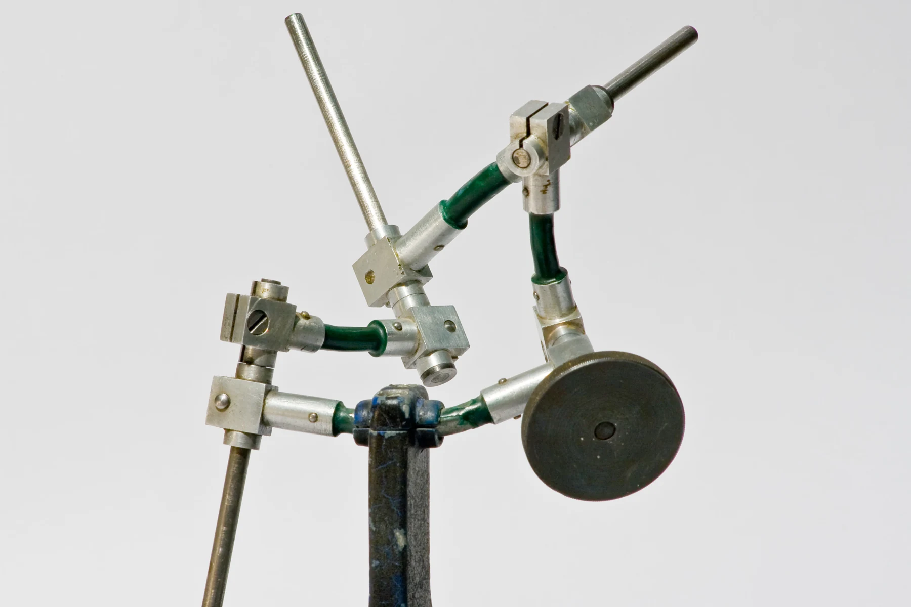
The reference photograph above shows a spatial four-bar linkage. Our door mechanism was a planar team build; the photograph is a related mechanism reference, not our prototype.
Keeping the loop closed
A planar four-bar can be described by the vector loop:
r₁ connects the fixed pivots, while r₂, r₃, and r₄ describe the moving links with directions chosen around the loop. Their positions must satisfy this closure as the mechanism moves. Changing a link length or pivot location changes the motion allowed by that geometry.
We turned the layout into physical links, pivots, and joints and built a working door-opening mechanism. Seeing the assembly move helped me understand how a small geometric change can affect the whole motion.