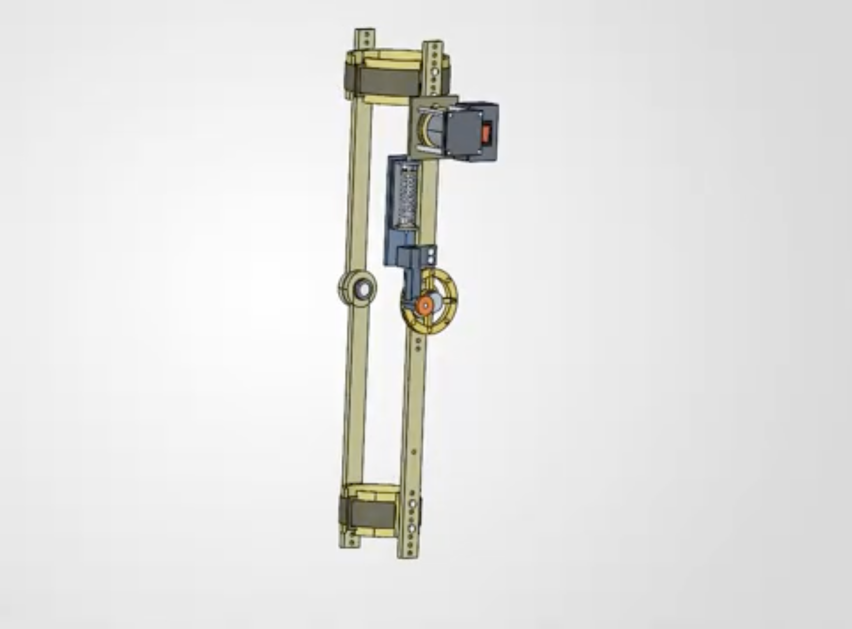
Starting with a passive mechanism
This team project began as a passive spring-assisted knee concept. We wanted to understand how spring placement and joint geometry changed the assistance available through the motion. That meant looking at the force path and usable movement together.
I modeled and refined the mechanism in SolidWorks, using ANSYS and interference checks to identify layouts that could move through the intended flexion range. Moving a spring attachment could change both the assistance and the clearance, so those decisions needed to be checked together.
From spring force to knee assistance
A first-order model connects spring extension to force, and force to the assistance torque:
Fₛ is spring force, kₛ is spring stiffness, and Δℓ is extension from the spring’s unloaded length. The perpendicular moment arm r⊥ changes with knee angle θ. These equations explain why the attachment geometry matters: the same spring force can produce a different torque at a different angle.
This is an idealized relationship for understanding the design. Friction, cable routing, spring behavior, and the physical assembly still need bench measurements.
Extending the design into an actuated brace
We developed the passive concept into an actuated knee assistance system that tracks knee angle and adds controlled cable-and-spring assistance while the user extends actively.
The system definition includes adjustable rails and cuffs, the motor drive, angle sensing, protected power, and an independent manual release. The CAD screenshot above shows this actuated layout. The release is part of the mechanical design, rather than relying only on a software command to stop assistance.
Where the project reached
The design reached a procurement-ready system, with bench checks defined for angle accuracy, spring force, assisted motion, jam release, faults, and cycle life. Our team placed in the top 5 of 70 teams nationwide in the Incubate X Prosthetic Challenge.
The completed work covers the design and system definition. Procurement and bench testing are the next steps; there are no clinical or human-performance results to report from this work.